
Proper Operation
Learn how your appliance is supposed to operate so you can determine if it is malfunctioning.
This page contains affiliate links. For more information visit our
FTC disclosure page.
- Visit our sponsor for parts:

GE Electronic Icemaker Components
To access to the icemaker control board and internal components remove the plastic plug at top of the cover to reveal a Phillips head screw holding cover in place.
This icemaker has no replacement parts available and is not intended to be repaired.
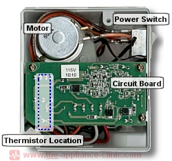
The ON/OFF rocker switch is mounted on right side of icemaker control housing when facing the circuit board.
The green LED indicator light is mounted on right side of cover to show when power is on. It is also used to indicate icemaker fault conditions, like an open or shorted thermistor, or a harvest cycle that takes longer than 30 minutes. Fault mode is indicated when the LED blinks 1/2 second on, 1/2 second off repeatedly until icemaker is turned off.
The electronic control board is secured by three Phillips screws within the control housing. All wiring uses plug-on terminals. The control board is not sold separately.
The unit's temperature thermistor is mounted in the mold body directly behind the control housing. It has two functions: 1) to measure ice temperature during freezing, 2) to determine water level during the fill cycles. The icemaker thermistor has a negative coefficient. That is, an increase in temperature will cause a decrease in resistance.
The sensing arm or 'paddle' moves laterally (horizontally) not up and down. A full ice bucket will prevent the arm from moving out to the fully extended position, stopping the next harvest cycle until ice cubes are removed and the arm is able to swing out completely
The electronic control board contains two hall effect sensors (similar to electronic reed switches). One switch is activated by a magnet attached to the end of the ejector arm to determine if the motor has reached the 'home' position. Another magnet attached to the sensing arm is used to determine if the that arm has reached the fully extended position. (ie. Ice has not prevented it from moving outward to the fully extended position).
Click the banner to visit our sponsor to purchase parts:
